Hydro-Powered Automatic Water Tap Control and Monitoring System
A touch-free water tap that opens when an IR sensor detects hands and closes when they move away. It powers itself from the water flow through a built-in micro hydro generator.
- My role
- Team member
- Controller
- ATmega328P (Arduino Uno platform)
- Power
- 3.6 V micro hydro generator + Li-ion battery
- Report
- August 2017
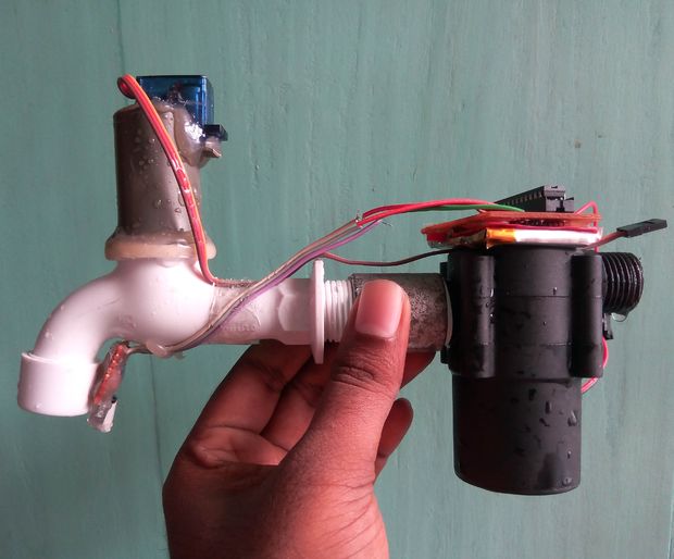
Overview
A team project I contributed to as a member.
Design and construction of a hydro-generated automatic water tap control and monitoring system. An IR sensor under the spout detects hands, and a micro servo turns the tap's valve open or closed, so the tap is never touched.
The system needs no external power source: a small hydro generator in the water line produces electricity from the flowing water and charges a Li-ion battery that runs the electronics.
Problem Statement
Ordinary taps are opened and closed by hand. Water runs to waste between opening the tap and washing, and whenever someone forgets to close it. Turning the handle hard also wears out the valve.
Touching a shared tap handle after washing spreads germs. Most commercial sensor taps solve this but need batteries or mains power.
Objectives
Open and close a standard water tap automatically, without any physical contact.
Reduce water wastage by letting water flow only while hands are under the tap.
Make the system self-powered by generating its own electricity from the water flow.
System Architecture
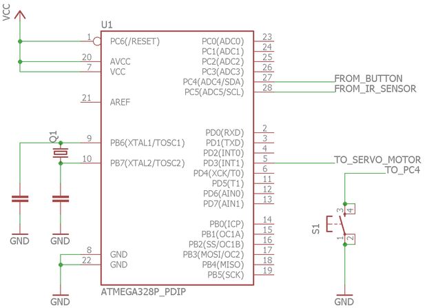
Sensing: an IR LED shines downward and an IR phototransistor next to it picks up the light reflected from hands. The receiver output goes to an analogue input of the microcontroller (PC5 / ADC5), which converts it to a digital value and compares it with a preset threshold.
Actuation: above the threshold, the microcontroller signals a micro servo (on PD3) that turns the tap's valve stem 90° and water flows. When the hands are removed, the servo turns the valve closed again. A push button on PC4 toggles the tap on and off manually.
Power: the micro hydro generator feeds an LM7805 regulator, because the TP4056 Li-ion charging module tolerates at most 5.5 V. The charger keeps the battery topped up, and the battery supplies the microcontroller.
Hardware and Software
Controller: ATmega328P — the microcontroller of the Arduino Uno — on its own board with an external 16 MHz crystal, programmed through an Uno board.
Sensor: IR transmitter LED (forward-biased, with a 220 Ω resistor) and IR receiver (reverse-biased, with a 56 kΩ resistor), soldered on a small PCB with three wires for VCC, GND and signal.
Mechanics and power: micro servo motor, 1.25-inch plastic pipe, 3.6 V G ½" micro hydro generator, G ½" female screw thread with thread-seal tape, LM7805 regulator, TP4056 charging module and a polymer Li-ion battery.
Monitoring parts in the hardware list: a YF-S201 Hall-effect water flow meter (pulse frequency in Hz = 7.5 × flow in L/min, about 450 pulses per litre, 1–30 L/min, ±10%) and a 16×2 character LCD.
Software: the program was written in the Arduino IDE and uploaded to the microcontroller.
Methodology
1) Modified the tap: removed the handle and glued the servo horn onto the valve stem.
2) Set the servo horn to the closed-valve position by hand, fitted the servo into a plastic pipe and mounted the pipe on the tap. The horn must match the stem exactly or the valve will not turn.
3) Sealed the pipe to the tap and fixed the servo to the pipe with hot glue on all sides to keep water out.
4) Fitted the female screw thread to the micro hydro generator with seal tape, then connected the modified tap to the other side of the thread.
5) Built the IR sensor circuit on a small PCB, trimmed the leads, and glued the sensor module under the spout.
6) Built the ATmega328P control circuit with the 16 MHz crystal and push button, wired the generator → LM7805 → TP4056 → Li-ion battery chain, uploaded the program and tested the complete system.
Results
The finished tap was tested under different conditions and opened and closed as intended.
Measured in the report: with the tap on the third floor of a six-storey building, the hydro generator gave an output of around 6 V — enough to charge the Li-ion battery.
The simple IR sensor worked reliably indoors, but sunlight interferes with it outdoors. The report does not include measured water savings or response times.
Conclusion and Future Work
Because the tap runs on energy from its own water flow, there is no extra operating cost, and the tap cannot be left running by mistake.
Limitations noted in the report: enough water pressure is needed to generate sufficient power, and the initial cost is high. A hydro generator with a built-in charging circuit would simplify the design.
Proposed improvements: use the flow sensor to measure water use, add IoT functions for remote control and monitoring, and integrate a water-quality sensor.
Diagrams & Pictures
Pictures
- Arduino program (source code)To be added